Software Engineering 2071
Attempt any Ten questions.(10 x 6 = 60)
1. What is software? Discuss generic products and bespoke products with example. Discuss functional and non-functional system properties with example.
Software is an organized collection of computer programs and associated documentation. A software system consist of a number of several programs, configuration files which are used to set of these programs and system documentations which describe the structure of system and user documentation which explain how to use the software.
Generic products and Bespoke products
Generic Products: These are stand-alone systems that are produced by a development organization and sold on the open market to any customer who is able to buy them. (i.e. developed to be sold to a range of different customers). e.g. Databases, Office packages, Drawing Packages etc.
Bespoke (custom) Products: These are the systems which are commissioned by a particular customer. A software contractor develops the software especially for that customer. (i.e. developed for a single customer according to their specification). e.g.: Control system for electronic device, software to support particular business process.
Functional and Non-functional system properties
Functional Property: These appear when all the parts of a system work together to achieve some objective. For example, a bicycle has the functional property of being a transportation device once it has been assembled from its components.
Non-functional Property: These relate to the behaviour of the system in its operational environment. They are often critical for computer-based systems as failure to achieve some minimal defined level in these properties may make the system unusable. Examples are reliability, performance, safety, and security.
2. What is software process model? Discuss reuse-oriented development in detail.
A software process model is an abstract representation of a process. It presents a description of a process from some particular perspective.
The reuse-oriented development is where they reuse programming or software in previous projects or existing software components. Reuse-oriented development is based on systematic reuse where systems are integrated from existing components. This development can reduce the overall cost of software development and it can also save time because each phase of the process builds on the previous phase which has already been refined.
The general process model for reuse based development is shown in figure below:

1. Requirement Specification: All possible requirements of the system to be developed are captured in this phase.
2. Component Analysis: According to given requirement, component is selected to implement that requirement specification. That is not possible the selected component provide the complete functionality, but that is possible the component used provide some of the functionality required.
3. Requirement Modification: Information about component that is selected during component analysis is used to analysis requirement specification. Requirements are modified according to available components. Requirement modification is critical then component analysis activity is reused to find relative solution.
4. System design with reuse: During this stage the design of the system is build. Designer must consider the reused component and organize the framework. If reused component is not available then new software is develop.
5. Development and Integration: Components are integrated to develop new software. Integration in this model is part of development rather than separate activity.
3. Discuss the importance of project management . What are the different sections of project plan?
Software Project Management (SPM) is a proper way of planning and leading software projects. It is a part of project management in which software projects are planned, implemented, monitored and controlled.
Project management focuses on developing a product that will have a positive effect on an organization. Without project management, a software development team may begin working on a project without any clear vision or guidance, resulting in more frequent errors and confusion. Part of project management involves making everyone involved aware of the purpose of the project and what steps are required to meet the end goal.
The project plan sets out the resources available to the project, the work breakdown and a schedule for carrying out the work. The details of the project plan may vary depending on the type of project and organisation. However, most plan include following sections:
1. Introduction: Objectives of the project and sets out the constraints (i.e budget, time, etc.) that effect the project management.
2. Project organisation: Development team hierarchy, people involved and their roles.
3. Risk analysis: Possible project risk and the risk reduction strategies that are proposed.
4. Hardware and software resources requirements: Specifies the hardware and sw required to carry out the development with their prices and delivery schedule.
5. Work breakdown: Whole project into activities with milestones and deliverables associated with each activity.
6. Project schedule: Dependencies between activities, estimated time required and people & resources required for activities.
7. Monitoring and reporting mechanisms: Project monitoring mechanisms and management report that should be produced.
4. Discuss requirements elicitation and analysis activity of requirements engineering process.
Requirements elicitation and analysis is a process of interacting with customers and end-users to find out about the domain requirements, what services the system should provide, and the other constrains.
The requirements elicitation and analysis has 4 main process:
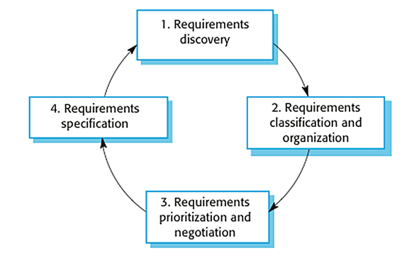
1. Requirements Discovery: It’s the process of interacting with, and gathering the requirements from, the stakeholders about the required system and the existing system (if exist). It can be done using some techniques, like interviews, scenarios, prototypes, etc, which help the stockholders to understand what the system will be like.
2. Requirements Classification & Organization: It’s very important to organize the overall structure of the system. Putting related requirements together, and decomposing the system into sub components of related requirements. Then, we define the relationship between these components.
3. Requirements Prioritization & Negotiation: This activity is concerned with prioritizing requirements and finding and resolving requirements conflicts through negotiations until you reach a situation where some of the stakeholders can compromise.
4. Requirements Specification: It is the process of writing down user and system requirements into a document. The requirement should be clear, easy to understand, complete and consistent.
5. Discuss evolutionary prototyping and throw-away prototyping in the software process.
Evolutionary prototyping
In this method, the prototype developed initially is incrementally refined on the basis of customer feedback till it finally gets accepted. It helps us to save time as well as effort. That's because developing a prototype from scratch for every interaction of the process can sometimes be very frustrating.
This model is helpful for a project which uses a new technology that is not well understood. It is also used for a complex project where every functionality must be checked once. It is helpful when the requirement is not stable or not understood clearly at the initial stage.
![Evolutionary prototyping model (Adapted from [11] ) | Download Scientific Diagram](https://www.researchgate.net/profile/Shahnita-Shaharin/publication/301945976/figure/fig6/AS:668712415797266@1536444872797/Evolutionary-prototyping-model-Adapted-from-11.png)
Fig: Evolutionary prototyping model
Throw-away prototyping

Fig: Throw-away prototyping model
6.Why do we need formal specification? Discuss behavioral specification in detail.
A formal software specification is a statement expressed in a language whose vocabulary, syntax, and semantics are formally defined. It is a technique for unambiguous specification of software to be build. The specification languages cannot be based on natural language; it must be based on mathematics because natural language specification are informal and usually contain ambiguities.
Formal methods are intended to systematize and introduce rigor into all the phases of software development. This helps us to avoid overlooking critical issues, provides a standard means to record various assumptions and decisions, and forms a basis for consistency among many related activities. By providing precise and unambiguous description mechanisms, formal methods facilitate the understanding required to coalesce the various phases of software development into a successful endeavor.
Behavioral specification
The simple algebraic technique can be used to describe interfaces where the object state changing depending on the previous operation result. Where this condition holds we say it the behavior properties of system. The specification which is used to specify such type of system property is called behavioral specification.
The object state of the subsystem changes on the result of operations in the object or while interacting with other sub-system objects. The changes of the state of object is called behavioral characteristics of the system. The behavioral state of the formal specification is represented by model-based approach and is expressed as a state model.
Basic types of behavioral specification:
1. Abstract model specifications: defines operations in terms of well-defined mathematical model.
2. Algebraic specifications: defines operations by a collection of equivalence relations.
3. State transition specification: defines operations in terms of states and transitions.
4. Axiomatic specifications: defines operations by logical assertions.
7. What are the advantages of designing and documenting software architecture? What is repository model?
The advantages of designing and documenting software architecture:
1. Stakeholder communication: Architecture may be used as a focus of discussion by system stakeholders.
2. System analysis: Well-documented architecture enables the analysis of whether the system can meet its non-functional requirements.
3. Large-scale reuse: The architecture may be reusable across a range of systems or entire lines of products.
Repository Model
A repository model is a system that will allow interfacing sub-systems to share the same data. Sub-system must exchange data so that they can work together effectively. This may be done in two ways:
1. All shared data is held in a central database that can be accessed by all subsystems. It is called repository model.
2. Each sub-system maintains its own database. Data is interchanged with other sub-systems by passing messages to them.
Example: CASE Toolset

Advantages:
- It is an efficient way to share large amounts of data. There is no need to transmit data explicitly from one sub-system to another.
- Sub-systems that produce data need not be concerned with how that data is used by other subsystems.
- Activities such as backup, security, access control and recovery from error are centralized.
Disadvantages:
- It is a compromise between the specific needs of each tool. Performance may be adversely affected by this compromise.
- Evolution may be difficult as a large volume of information is generated according to an agreed data model.
- Different sub-systems may have different requirements for security, recovery and backup policies. The repository model forces the same policy on all subsystems.
8. Discuss the use of control models. Differentiate between centralized control and event based control.
Control models are models deployed in software engineering that are concerned with the control flow between the subsystems. They are distinct from the system decomposition model.
Centralized Control Model
Centralized model is a formulation of centralized control in which one subsystem has overall responsibility for control and starts and stops other subsystems. It is a control subsystem that takes responsibility for managing the execution of other subsystems. Centralized models are classified into call-return and manager model.
1. Call-return Model: In call-return model, it is a model which has top-down subroutine architecture where control starts at the top of a subroutine hierarchy and moves downwards.

The call-return model is illustrated in above figure. The main program can call Routines 1, 2 and 3; Routine 1 can call Routines 1.2 or 1.2; Routine 3 can call Routines 3.1 or 3.2; and so on.
2. Manager Model: Manager model is applicable to concurrent systems. One system component controls the stopping, starting and coordination of other system processes.

Event-based Control Model
Event-based models are those in which each sub-system
can respond to externally generated events from other
subsystems or the system’s environment. It is a system
driven by externally generated events where the timing of
the events is out with the control of the subsystems which
process the event.
Event-based models are classified into broadcast and interrupt-driven models.
1. Broadcast models: In these models, an event is, in principle, broadcast to all sub-systems. Any sub-system, which is designed to handle that event, responds to it.

2. Interrupt-driven models: These are exclusively used in real-time systems where an interrupt handler detects external interrupts. They are then passed to some other component for processing.

9. Discuss sequence diagram with suitable example.
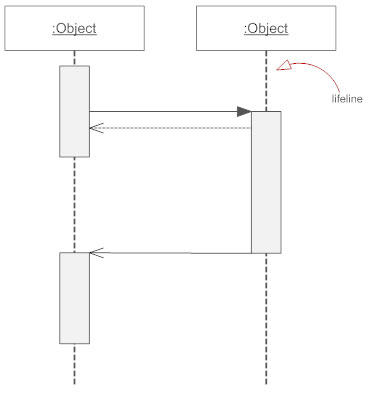
Sequence Diagrams are interaction diagrams that detail how operations are carried out. They capture the interaction between objects in the context of a collaboration. Sequence Diagrams are time focus and they show the order of the interaction visually by using the vertical axis of the diagram to represent time what messages are sent and when.
Some basic sequence diagram notation are:
1. Class Roles or Participants: Class roles describe the way an object will behave in context. Use the UML object symbol to illustrate class roles, but don't list object attributes.
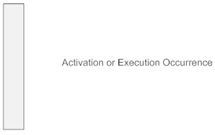
2. Activation or Execution Occurrence: Activation boxes represent the time an object needs to complete a task. When an object is busy executing a process or waiting for a reply message, use a thin gray rectangle placed vertically on its lifeline.
3. Messages: Messages are arrows that represent communication between objects. Use half-arrowed lines to represent asynchronous messages. Asynchronous messages are sent from an object that will not wait for a response from the receiver before continuing its tasks.
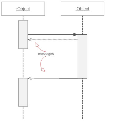
4. Lifelines: Lifelines are vertical dashed lines that indicate the object's presence over time.
Example: Sequence diagram for ATM system

10. What is verification and validation? Briefly explain verification and validation planning.
Verification is the process of evaluating the product during the development to find out whether they meet the specific requirements (functional and non-functional requirements).
Validation is the process of checking the product after development to determine whether software meets the customer expectations and requirements.
The ultimate goal of verification and validation process is to establish confidence that the software system is "fit for purpose".
Verification and Validation planning
Validation and verification is an expensive process and more than the half the system development budget may be spend on validation and verification process. So, careful planning is needed for validation and verification (V & V).

Fig: Test plans as a link between development and testing
It breaks down system V & V into a number of stages. Each stage is driven by tests that have been defined to check the conformance of the program with its design and specification.
We should decide on the balance between static and dynamic approaches to V & V, draw up standards and procedures for software inspections and testing, establish checklists to drive program Inspections and define the software test plan.
Test planning is concerned with establishing standards for the testing process. It helps managers to allocate resources and estimate testing schedules, test plans are intended for software engineers involved in designing and carrying out system tests. It helps technical staff get an overall picture of the system tests and place their own work in this context.
11. What is integration testing? Differentiate between top-down and bottom-up integration testing.
Integration testing is defined as a type of testing where software modules are integrated logically and tested as a group. A typical software project consists of multiple software modules, coded by different programmers. The purpose of this level of testing is to expose defects in the interaction between these software modules when they are integrated. Integration Testing focuses on checking data communication amongst these modules.
Difference between top-down and bottom-up integration testing
Top Down Integration testing | Bottom Up Integration testing |
Top Down Integration testing is one of the approach of Integration testing in which integration testing takes place from top to bottom means system integration begins with top level modules. | Bottom Up Integration testing is one of the approach of Integration testing in which integration testing takes place from bottom to top means system integration begins with lowest level modules. |
In this testing the higher level modules are tested first then the lower level modules are tested and then the modules are integrated accordingly. | In this testing the lower level modules are tested first then the higher level modules are tested and then the modules are integrated accordingly. |
In this testing stubs are used for simulate the submodule if the invoked submodule is not developed means Stub works as a momentary replacement. | In this testing drivers are used for simulate the main module if the main module is not developed means Driver works as a momentary replacement. |
Top Down Integration testing approach is beneficial if the significant defect occurs toward the top of the program. | Bottom Up Integration testing approach is beneficial if the crucial flaws encounters towards the bottom of the program. |
The complexity of this testing is simple. | The complexity of this testing is complex and highly data intensive |
It works on big to small components. | It works on small to big components. |
In this approach Stub modules must be produced. | In this approach Driver modules must be produced. |
12. Write short notes on:
a. Functional Point
b. Source Code translation
a. Functional Point
Functional point is an element of software development which helps to approximate the cost of development early in the process. It may measure functionality from user's point of view.
Counting functional point (FP):
Step 1:
F = 14*scale, scale varies from 0 to 5 according to character of complexity adjustment factor (CAF).
Step 2:
CAF = 0.65 + (0.01*F)
Step 3:
Calculate unadjusted functional point (UFP)
Step 4:
Calculate functional point FP = UFP * CAF
b. Source Code translation
The simplest form of software re-engineering is source code translation where source code in one programming language is automatically translated to source code in some other language. The structure and organisation of the program itself is unchanged. The target language may be an updated version of the original language (e.g. COBOL-74 to COBOL-85) or may be a translation to a completely different language (e.g. FORTRAN to C).
Program translation process:

Fig: Program translation process