Digital Logic - Old Questions
1. Draw a block diagram, truth table and logic circuit of a 16 x 1 multiplexer and explain its working principle.
Answer
AI is thinking...
In 16 X 1 multiplexer:
Input lines 16 = 24 i.e. 4 Selection lines
Input lines will be I(0)- I(15)
Selection lines will be S0 - S3
Block Diagram
Truth Table

let us implement 16x1 Multiplexer using 8x1 Multiplexers and 2x1 Multiplexer. We require two 8x1 Multiplexers in first stage in order to get the 16 data inputs. Since, each 8x1 Multiplexer produces one output, we require a 2x1 Multiplexer in second stage by considering the outputs of first stage as inputs and to produce the final output.
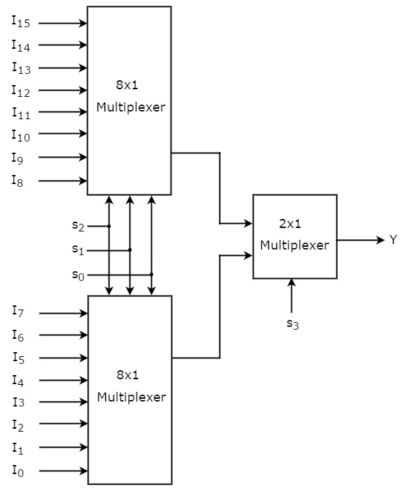
The same selection lines, s2, s1 & s0 are applied to both 8x1 Multiplexers. The data inputs of upper 8x1 Multiplexer are I15 to I8 and the data inputs of lower 8x1 Multiplexer are I7 to I0. Therefore, each 8x1 Multiplexer produces an output based on the values of selection lines, s2, s1 & s0.
The outputs of first stage 8x1 Multiplexers are applied as inputs of 2x1 Multiplexer that is present in second stage. The other selection line, s3 is applied to 2x1 Multiplexer.
- If s3 is zero, then the output of 2x1 Multiplexer will be one of the 8 inputs Is7 to I0 based on the values of selection lines s2, s1 & s0.
- If s3 is one, then the output of 2x1 Multiplexer will be one of the 8 inputs I15 to I8 based on the values of selection lines s2, s1 & s0.
Therefore, the overall combination of two 8x1 Multiplexers and one 2x1 Multiplexer performs as one 16x1 Multiplexer.