Digital Logic 2070
Long Questions:
AI is thinking...
Attempt any two questions: (2 × 10=20)
AI is thinking...
1. Design Magnitude comparator and also design a logic diagram for a 4 bit magnitude comparator.
AI is thinking...
2. What do you mean by ripple counters? Explain with timing diagram.
AI is thinking...
3. Explain the full subtractor with using decoder.
Full subtractor contains 3 inputs and 2 outputs (Difference and Borrow) as shown-

The truth table for full subtractor:

From the above truth table,
For the different functions in the truth table, the minterms can be written as 1,2,4,7, and similarly, for the borrow, the minterms can be written as 1,2,3,7.
Since there are three inputs and a total of eight minterms. So we need 3-to-8 line decoder. The decoder generates the eight minterms for A, B & Bin.
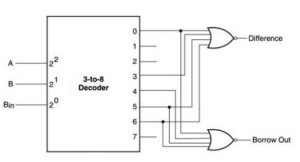
Fig: Full subtractor with 3-to-8 Decoder and NOR gates
AI is thinking...
Short Questions:
AI is thinking...
Attempt any eight questions: (8 × 5=40)
AI is thinking...
4. Design a half adder logic using only NAND gates.
Soln:
Input
variables: A & B, Output variables: sum and carry


Logic diagram of half adder using NAND gates only:

AI is thinking...
5. Convert the following decimal number into hexadecimal and octal.
a. 334
b. 225
AI is thinking...
6. Explain the K-map with three variables.
AI is thinking...
7. Explain the combination logic with examples.
Combinational circuit is a circuit which consist of logic gates whose outputs at any instant of time are determined directly from the present combination of inputs without regard to previous input. The combinational circuit do not use any memory.
There will be combination of input variable for inputs.
A combinational circuit can have number of inputs and number of outputs.
For e.g. adders, subtractors, decoders, encoders etc.

Fig: Block diagram of combinational circuit
Combinational logic circuit design procedure:
The problem is stated.
The number of available input variables and required output variables is determined.
The input and output variables are assigned letter symbols.
The truth table that defines the required relationships between inputs and outputs is derived.
The simplified Boolean function for each output is obtained.
The logic diagram is drawn.
Adders
Adders are the combinational circuits which is used to add two or more than two bits at a time.
Types of adders:
Half Adder
Full Adder
Half Adder:
A combinational circuit that performs the addition of bits is called half adder. This circuit needs two binary inputs and two binary outputs. The input variables designate the augend and addend bits; the output variables produce the sum and carry.

Fig: Block diagram
AI is thinking...
8. Differentiate between Multiplexer and demultiplexer.
AI is thinking...
9. Mention the difference types of shift register.
AI is thinking...
10.What do you mean by Ripple counters?
AI is thinking...
11. Explain the decoder and design with universal gates.
AI is thinking...
12. What do you mean by clocked RS flip-flop ?Explain
AI is thinking...
13. Write short note on (any two):
a) Flip flop
b) Synchronous Counter
c) Digital systems.
AI is thinking...